Drip Irrigation System design is a very interesting and oft searched subject for the farmers.
- Drip Irrigation System design is a very interesting and oft searched subject for the farmers.
- Why Have the Drip Irrigation System
- What Goes Into a Drip Irrigation System
- Information Required Beforehand
- Brief on Water Requirement
- Irrigation Time
- Step-wise Plan For Irrigation System
- Layout Details of Drip System in the Field
- Emitter Selection
- Distribution Components
- Size and length of mainline, sub-main, and lateral pipes
- Pumping and filtration requirement
- Chemical fertigation
- Survey Plan
Why Have the Drip Irrigation System
Drip irrigation systems avoid wastage of water and conserve precious gifts. This type of irrigation system is obviously not indicated for rain-fed agricultural activities. However considering the severe depletion of water resources the world over, drip irrigation is gaining ground. The motto of drip irrigation is one drop more crop.
It is easy to install, easy to design, can be very inexpensive, and can reduce disease problems associated with high levels of moisture on some plants.
Drip irrigation system allows what is termed fertigation i.e. fertilization plus irrigation. Fertilizer is sent mixed with irrigation water to plants. Such fertigation not only economizes but also adds effectiveness and efficiency to the fertilization process. The first is that the water soaks into the soil before it can evaporate or runoff. The second is that the water is only applied where it is needed, (at the plant’s roots) rather than sprayed everywhere.
For more on why have the drip irrigation system, our blog DRIP IRRIGATION provides greater insight.
What Goes Into a Drip Irrigation System
To get to know what are all bundled in our drip irrigation system, let us refer to the following representative figure:
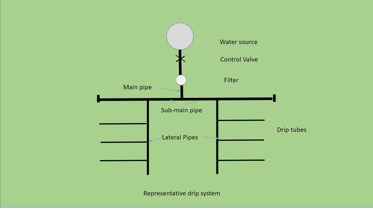
So we require a water source, a control valve (actually we may require several control valves for each of our sub-mains), main pipe, sub-main pipes, lateral pipes, and then the drip tubing (there are different types – use as required).
Information Required Beforehand
The first step a farmer needs is to collect the following information:
- Layout of the area.
- Details of the water source and soil type.
- Type of crop proposed, crop period, season, plant canopy area, etc.).
- Climatic data (rainfall, temperature, evapotranspiration, etc.).
- Water requirement
Brief on Water Requirement
The water requirement of plants depends on many factors such as temperature, humidity, soil type, wind velocity, growth stage, shade/sun, etc. Plants absorb soil moisture and transpire it to the atmosphere during the process of photosynthesis. Some amount of water is retained in the plant tissue and the rest of the soil moisture gets evaporated into the atmosphere.
Drip irrigation involves the frequent application of water, even on a daily basis. Therefore, the water requirement of the plant per day is equivalent to the rate of potential evapotranspiration per day.
Evapotranspiration: the quantity of water transpired by the plants plus the quantity of water retained in the plant tissue and water evaporated from the soil surface. The reference values for evapotranspiration are normally available for a particular area at the nearest meteorological observatory.
Water requirement (WR) can be expressed by the following expression:
WR (Liters per day) = ET x Kc x Cp x Area, where
ET is evapotranspiration (mm per day),
Cp is canopy factor,
Area in sq. meter
If specific crop factor Kc values are not available, then it can be assumed as one.
The canopy factor is the percentage of area covered by plant canopy (foliage).
The area for orchards is the multiplication of the distance from the plant to plant (m) and distance from row to row (m). For row plantations, the unit area can be taken to calculate water requirements.
Example: Calculate peak water requirement – plants spacing of 2 m by 2m. Assume peak ET for the area as 6 mm per day, crop factor as 0.9, and canopy factor 0.7.
Peak water requirement per day = 6 x 0.9 x 0.7 x 2 x 2 = 15.12 liters per day per plant
Actual daily water requirements will depend on the daily rate of evapotranspiration which is less during winter and higher in summer.
Irrigation Time
Irrigation time is defined as the total water flow period through the emitter required such that by the plant receives the daily water required. We can write this as the expression:
Irrigation time (hours/day) = Daily Water requirement (liters per day) / application rate (liters/hour)
The application rate would be set by the emitters selected e.g. 2, 4, 8 liters per hour.
Example: Daily water requirement = 10 liters per day; drip system discharge rate = 4 liters per day.
Irrigation time (hours/day) = 10/4 = 2.5 hours/day
Step-wise Plan For Irrigation System
Armed and aided by the above information, we now plan a customized drip irrigation system:
- Detail of layout of the system in the field.
- Emitter selection and placement.
- Size and length of mainline, sub-main, and lateral pipes.
- Pumping and filtration requirement.
- Operating schedule for irrigation.
- Material and cost estimate.
Layout Details of Drip System in the Field
The following survey inputs are required to prepare an accurate layout of any area (size, shape, and slope) for the design of a micro-irrigation system:
- Position of water source (tank, well, reservoir, pond, river, stream, existing pump, pipeline, etc.).
- Size, volume, flow rate, and height above ground level or depth from the ground surface or water source.
- Pump details for the existing pump e.g. suction, delivery, actual discharge, and head, operating time, pump HP, expected discharge, and head.
- Quality of water including any impurities in water (algae, sand /silt, etc.).
- Water analysis report.
- The details of existing or future crops.
- Crop spacing, number of plants and number of rows, crop duration, expected canopy, rainfall, evapotranspiration, etc.
- Soil analysis report.
- Location of farmhouse large trees, rocks, etc.
Emitter Selection
Emitters regulate and assure a uniform rate of flow of water. These are (drippers) are sometimes inbuilt in the tubing and also attached to the tubing by picking a hole in it and inserting an emitter. Emitters are classified by type of making.
Long Path Emitters have a small diameter and rather a lengthy path. This reduces the water pressure and gives a uniform flow. Short-Path Emitters have shorter water paths. These work well on low-pressure drip systems but are prone to clogging. The Tortuous Path or Turbulent Path Emitter is somewhat like the Long Path one but has many sharp turns and obstacles in the path. This reduces the need for long path length. The diameter is larger. The diaphragm emitter uses a flexible diaphragm to reduce the flow and pressure. This type is more accurate in controlling the flow and pressure. Drip-line type is a tube with factory preinstalled emitters. The emitters are molded inside the tubing. The emitters are uniformly distributed throughout the length of the tubing. Drip-line is laid on the surface only.
Emitters come in a variety of different flow rates. The normal values are 2.0, 4.0, or 8.0 liters/hour (liters per hour). For sand, we should use a 4.0. Normally, it is preferred to use 2.0 liters per hour emitters for better absorption of water as it comes out of the emitter.
Distribution Components
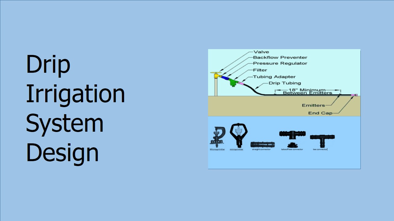
- Valves: A) Isolation valves – required to isolate water source from the drip system for any maintenance work. Such valves are manually operated. B) Control Valve – can be manual or automatic. The purpose is to turn on and off the flow of water into a particular drip circuit.
- Back flow Preventer: it is required in order that no dirt or any other damaging material is sucked back into the water source.
- Pressure regulator: this is a valve with a pressure sensor that controls the opening of the valve. A control valve can also be used by manual partial opening.
- Filter: it is for cleaning the water so that emitters do not get clogged.
- Emitters: already discussed.
- Main: it is the pipe that connects the water source to the main control valve. In case PVC is used for the main pipe take care to bury it in the earth as sunlight damages the PVC pipe.
- Sub-Main and Lateral: this terminology in some places is used interchangeably. The purpose is to connect the control valve to the drip emitters.
- Drip tube fittings: these are different types of fittings to connect drip lines in the way required.
- Air Vent: these are required to allow air to escape when the system is turned on. It also prevents air from being sucked into the emitters when the system is turned off.
- Flush valves or end cap: The end cap is put at the end of the drip line so that water does not run out. End caps make the water pressure uniform. Flush valves are put at the end of the sub-main and lateral pipes to regularly flush out any algae or chemicals remaining so as not to clog the drippers.
Size and length of mainline, sub-main, and lateral pipes
We have selected suitable emitter type and flow rates in required liters per minute based on:
- type of crop,
- water requirement,
- operating time,
- soil type, and
- water quality.
Flow carried by each lateral line
Q1 = Discharge of one emitter x No. of emitters per lateral
Flow carried by each sub-main Q = Q1 x number of lateral lines per sub main
Flow carried by main Q = Q1 x number of sub-main
The diameter of the main, sub-main, and laterals are chosen based on the hydraulics of pipe flow.
The length and size of lateral lines are determined based on the lateral line flow rate for the field size. Similarly, the size and length of the sub-main pipe are determined. (Each sub-main is an individual unit with its own control valve.) The whole area is then divided into different sub-main units. The number of sub-main units that can operate at any one time is based on the existing pumping/water source capacity. Sections should be designed such that the discharge is similar for all the sections.
The mainline is then planned to connect all the sub-mains by taking the shortest possible route. The length of the main pipe can be determined based on the flow rate so that frictional head loss is within specified limits and the total pressure head required for the system is within pump/water source capacity.
Pumping and filtration requirement
If there is no pump, then the pump requirement is worked out from the total discharge and pressure head required for the system. How to determine pump capacity has separately been described in our blog on same.
Depending on the flow rate and water quality, a suitable filtration device is selected.
The total quantity of all the components is calculated from the layout to prepare a cost estimate.
Chemical fertigation
Drip irrigation systems only for irrigation purposes only would normally not be used. This is because drip technology gives us a very efficient and cost-effective alternative to fertilize our fields, plants, and crops. We have covered this topic in detail in our separate blog on our website.
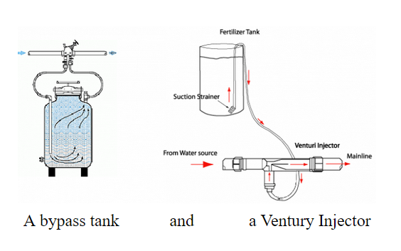
The figure below shows a typical method of applying fertilizers (liquid fertilizers) through the drip system. This block is placed after the main control valve and before the main filter. The mainline flow is forced to flow through the smaller pipes to which a venture is attached. Due to pressure differential venture sucks fertilizer solution and adds to water and whole then flows out into the drip lines.
Survey Plan
From the above information, a plan of the area surveyed can be prepared on a 1:1000 scale. For smaller areas, an appropriate scale can be used depending on the size of the area. The drip system layout can be prepared on this plan and then it can be used for installation.
Further reads:
- http://ecoursesonline.iasri.res.in/mod/page/view.php?id=2042
- https://myknowledgebase.in/fertigation-what-why-and-how/
- https://myknowledgebase.in/how-to-choose-a-pump-motor-for-irrigation/
Hi ; I have had opportunity to travel widely and have keen watched whatever farming practices the local farmers were engaged in. Back home been growing gerberas mostly in polyhouses, but outside in kitchen garden as well. i love these hardy perennials. good for business too if done in a routine orderly scientific manner. Also engaged in farming of wheat and organic vegetables on a small scale for me and family. My service profile has been that of an electronic and telecom engineer and now am engaged in web site creation and blogging.
Kindly sir sent me such types of data on advance automated irrigation system plz my email is Umerfayyaz013@gmail.com…please humble request
The article was very informative to read. I would like to thank you for such a great article.I found global drip irrigation manufacturer is one of the best company who provides a drip irrigation at affordable price.
personally I have not used components of this company. there are many more companies. Jain Irrigation is a well known in this field. would appreciate some more info on this from swati.